Introduction to Embedded Systems :: CSCI 255
Lab Assignments
Lab 2 -- Logical Circuits
HOME SYLLABUS HOMEWORK LABS LINKS NOTES
|
Circuit #1 – Two-bit equalityDesign a two-bit equality function. The function should return true only when the two input bits are the same value (both 0 or both 1). Build a circuit that lights an LED if P1.6 (LSB) and P1.0 (MSB) have the same value 1a) Show the truth table. 1b) Give the Boolean expression for the circuit. 1c) Draw a diagram of the circuit you intend to build (using normal gate notation). 1d) Build your circuit. 1e) Load program to CCS to test circuit 1f) Show your working circuit to Clint, Matt or Damian. How does the answer look like?
Circuit #2 – Three-bit majorityDesign a three-bit majority function. The function returns true whenever the majority of its bits are 1. The signals are assigned as: P1.0 (LSB/Bit0), P1.1 (Bit1) & P1.6 (MSB/Bit2). 2a) Show the truth table. 2b) Give the unminimized sum-of-products expression. 2c) Show how you minimized the sum-of-products expression including the final expression for your intended circuit. 2d) Draw a diagram of the circuit you intend to build (using normal gate notation). 2e) Build your circuit. 2f) Load program to CCS to test circuit 2g) Show your working circuit to Clint, Matt or Damian. How does the answer look like?
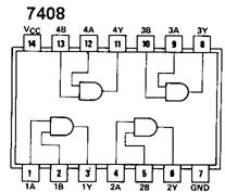
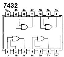
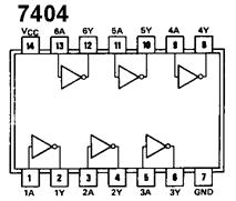
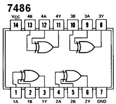
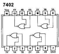
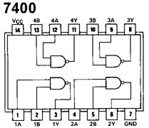
Circuit #3 – Rock, paper, scissors (Logisim only)Design a circuit that has three binary inputs for player A: Ar, Ap, As corresponding to player A playing rock, paper or scissors respectively. Similarly, there are three binary inputs for player B: Br, Bp, Bs. The winner is determined by the rules: rock smashes scissors, paper covers rock, scissors cuts paper. Your Logisim circuit should light up an LED labeled "A wins" if player A won the game or light up an LED labeled "B wins" if player B won. If there is a tie, neither of the LEDs should light up. If more than one of the inputs for a player is set to 1, any LED result is acceptable (the input is considered invalid). 3a) Find the minimal Boolean expression for the circuit. 3b) Implement and test your circuit in Logisim. Attach a printout of your Logisim circuit. Submit an electronic copy of your Logisim file to dvalles@mtech.edu by the due date. Extra-credit: implement the circuit in hardware. Show Clint, Matt or Damian your working circuit. P1.0 => As P2.0 => Bs GatesWe have 6 different ICs each containing a number of AND, OR, NOT, NAND, NOR, or XOR gates. Here are the schematics for each:
NOTE: each IC needs to be connected to power on pin 14 and ground on pin 7.
Copyright © 2011 by Keith Vertanen. |
Montana Tech --
College of Letters, Science &
Professional Studies -- Computer Science
Department
All Rights Reserved and Copyright
© 2013 by Damian Valles